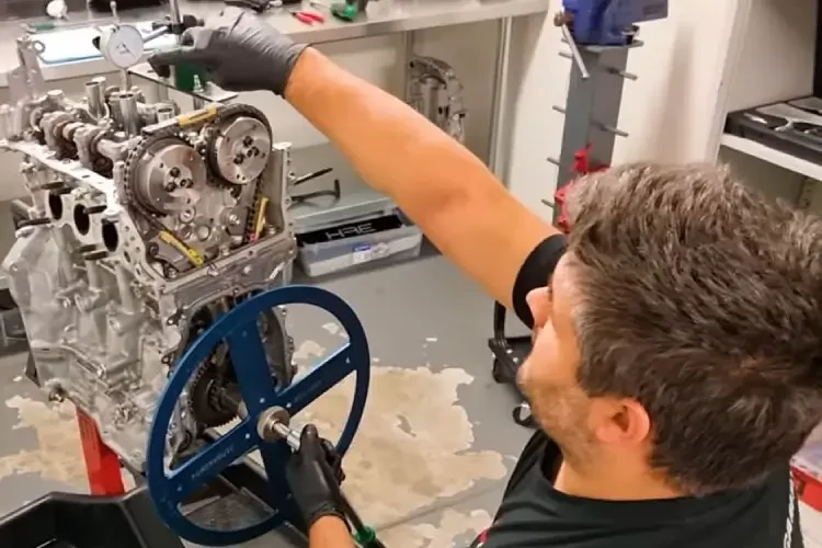
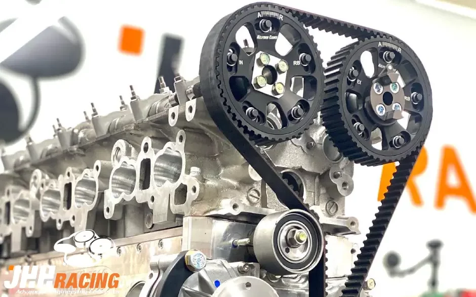
Sole Purpose of Degreeing Your Cams

Properly Degree Your Camshaft:
EQUIPMENT REQUIRED
All of our new camshafts are ground to exact specification using the latest CNC machining processes but there are other factors that can cause incorrect camshaft to crankshaft phasing. Such as:
- Cam or crank gears are incorrectly marked.
- Keyways are out of position on gears.
- Keyway in the crankshaft is miss-indexed.
- On SOHC & DOHC engines, milling the head or the block will retard the cam(s)
On SOHC rocker arm style engines, valve tip length, rocker geometry and base circle size will effect lobe separation, therefore effecting valve events. Thus properly degreeing your cam is essential.


Before You Start to Degree Your Cam
Assuming that you have carried out all of the preliminary static measurements and clearance checks for valve to valve, valve to piston, retainer to stem seal, cam to head casting, cam to con-rod, spring seat pressure, distance to coil bind at full lift etc, all parts are clean, and lightly oiled you are ready to start dialing in your camshaft.
Lifter Setup Instructions:
Be absolutely certain that you use the correct type of lifter for the camshaft that is being Degreed. Hydraulic lifters must never be used when degreeing cams, they can bleed down and give you false readings.
For Pushrod style engines this is easy, if your camshaft choice is hydraulic roller or hydraulic flat tappet, simply purchase a solid equivalent of your lifter. Install a pushrod that has an oil hole in it, so that the tip of the dial indicator locates properly in the end of the pushrod.
For over head cam engines that have hydraulic cam buckets, such as Nissan RB20 or Suzuki G13B or for over head cam engines with rocker arms and hydraulic lifters, such as Mitsubishi 4G63 or Nissan SR20, you will need to make a solid lifter that gives 0.1mm valve clearance when the cam is on the base circle. This is easiest done by pulling the plunger out of a hydraulic lifter and replacing it with a piece of turned silver steel (or similar) that sits properly inside the lifter body and is shaped at the valve end to clear the retainer and give a perfect flat contact to the valve tip.
(Remember to take it back out once you are done and put the proper hydraulic lifter back in)

Need More Time to Read!
Due to the level of information, we recommend to Download PDF direct to read when you need it.


